Update: All the design files and build information is now available at http://vonnieda.org/tc18
So, back in September the company I worked for, Displayware, ceased operations. That’s a fancy way of saying we went out of business. We did that because we ran out of money and didn’t have enough coming in to sustain the very meager workforce we had. Since then I’ve been unemployed, but mostly as a choice. I had money in the bank and was pretty burned out from the Displayware days so I decided to just take some time off and work on my own stuff and chill out.
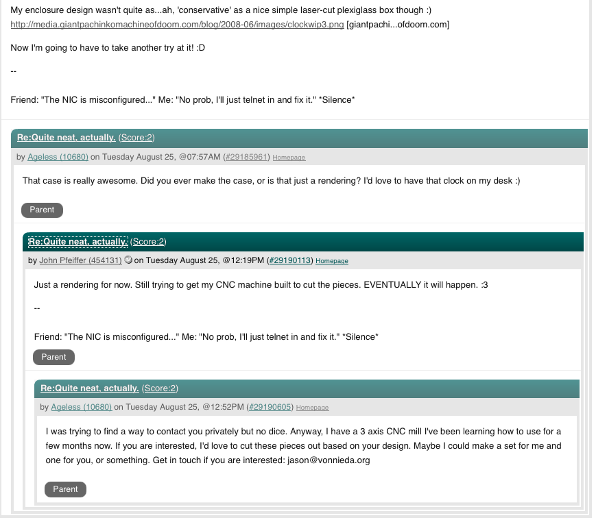
Right before that happened, Ladyada of Adafruit released her design for a clock based on an old Russian vacuum fluorescent display tube called an IV-18. I thought the clock circuit was really cool and the tube was great but I didn’t care much for the acrylic case. A day or two later I somehow came across a Slashdot article about it and was reading some of the comments when I saw someone comment on the case and post a picture of his own design.
THIS was the clock I wanted. I totally fell in love with the clock design and decided I must have one. This short conversation, via Slashdot comments, followed:
I never did hear back from John. I assumed he just never saw the comment. I spent some time trying to find an email address but eventually gave up and instead decided just to build it myself.
One of the things I decided to do when Displayware croaked was spend some time learning how to use my CNC mill. I bought a 3 axis mill in November f 2008 but had never really took the time to learn to use it. So, I spent many days getting up early, going out the garage and not coming out till Courtney got home from work. Those were very enjoyable days. My hands were dirty and cut, I was chopping up bits of metal and programming the mill and learning new stuff every day.
Eventually I got to the point that I felt like I could make stuff on the mill so the next step was to learn how to use CAD and CAM. I downloaded a CAD system and set to work learning how to use it. That took some time but eventually I was able to design the three metal plates I saw in the clock picture. Since all I had to work with was a single graphic from one angle I had to guess at a lot of things but I think I eventually came up with dimensions that were pretty close to original. The only real dimensions I was sure of were those of the tube itself, so I used what I knew about that to take educated guesses at the rest.
Once I had designs ready to go I bought some sheets of stainless steel and went about trying to cut the clock parts out from it. I used stainless because from the rendering of the clock that’s what I thought it was supposed to be. It turned out that it was nearly impossible for me to cut stainless on my little mill, so I switched to aluminum sheet and had much better luck. I cut the six plates out and sanded them a bit and set them aside.
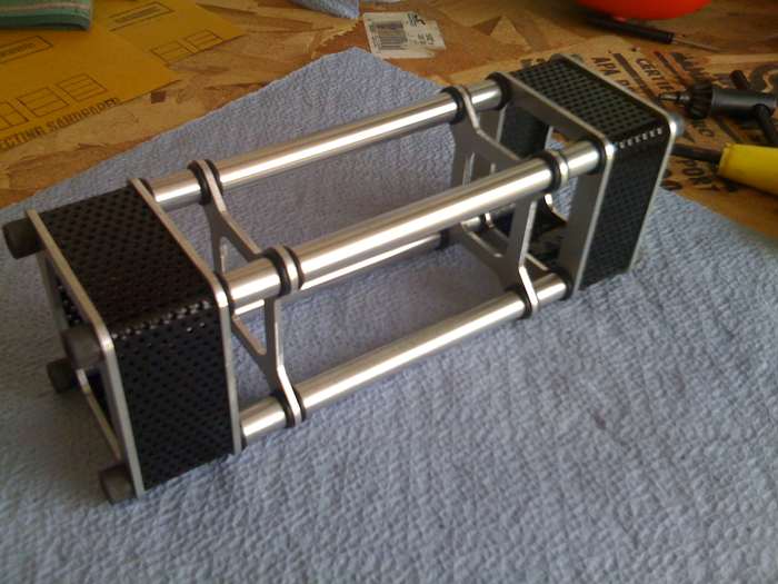
The next step was to make the metal pipes that connect the whole thing together. From the picture I thought these were polished aluminum so that’s what I started with. I bought some 6061 aluminum tube from Online Metals (where I get everything in this post) and set to trying to make it pretty. The process I eventually came up with is that I would take these 12″ sections of tube and stick one end into the chuck of my drill press. Set the speed to the lowest it would go and turn it on. Then I started with 250 grit sandpaper running up and down the spinning tube. Then 500 grit, then 1000, then 2000. After all that the tube is looking pretty smooth so I took some polishing compound to it and that really made it shine. It looked just like the picture.
I cut out 8 1/2″ sections and 4 4″ sections, drilled the small ones through to widen the inner diameter to 1/4″ and then tapped both ends of the larger ones so they would accept bolts.
The next step was to find a LOT of o-rings. If you look at the picture you’ll see there are 24 o-rings used between all the pieces of tube. It’s an awesome design element and I wanted to stick with it. Unfortunately, when I went to the plumbing store I could only find about 4-6 of the ones I needed and they were almost a buck a piece. The o-rings would cost more than the rest of the clock! Eventually I decided to check McMaster-Carr, who I had never ordered from before, and it turned out I could buy bags of 100 for something like $1.34 total. That worked!
The final step in the design was the black perforated metal sleeves around the ends of the clock. I had been worrying about these for a while. I figured I could get perforated metal just fine, and bend it into shape maybe, but I had no idea how I would connect it at the bottom and make it look nice. I started researching welding aluminum and I started looking for used TIG welders.
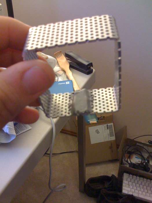
Since I couldn’t really afford any of the welders I was seeing I decided to just try hacking it together. What I ended up doing was using my mill to cut down a sheet of perforated aluminum to a 1″ thick strip about 14″ long. Then I made another CAD model. This one was of the shape that would fit inside this sleeve. I used this on the mill to cut out 2 3/4″ MDF forms which I glued together to make a single 1.5″ form. Using this form, a heavy pair of leather gloves and a heat gun I heated the aluminum up till it started to be easier to bend and then wrapped it around the form. I stuck a clamp on it to hold it shut and then I broke off a 1/2″ long strip of the same stuff from another piece. I put this inside the sleeve and super-glued it down to hold the sleeve together.
The super-glue worked okay but I knew I could pop it apart pretty easily if I wanted to. So, my next idea was JB Weld. This worked great! I mixed up some JB Weld, smeared it all over the inside of the sleeve and over the little brace and let it set up. After that it was rock solid. I sanded the whole thing down, spray painted it gloss black and called it good.

Once everything was dry I finally was able to put the whole thing together. After many weeks of work, here’s what I had.

I was pretty happy with it! I thought it looked quite a bit like what I was seeing in the image and for having started with nothing but a picture on the Internet I thought it was going pretty well. So, it was time to work on some electronics.
Somewhere along the way I ordered 5 of the IV-18 tubes from eBay. They were surprisingly cheap. I think I paid like $15. They actually came from Moscow, so that was pretty exciting. Unfortunately, they did not come with a datasheet and I didn’t really have a a pinout for the things. I spent an hour or two with a loupe and headache looking at all the little wires inside and figuring out a pinout. A day later the seller emailed me a datasheet. Oh well.
One of the enabling elements of this whole thing was that when Ladyada posted her clock design she also posted schematics and notes. This allowed me to learn about boost converters, which are circuits that allow you to take a very low voltage and make a very high voltage pretty easily. I knew about boost converters, but I had no idea they could be so easy to build. Ladyada’s designs really made that clear and she even posted a calculator for figuring out the proper values.
The IV-18 tube requires about 20v (volts) to light up and 50v really makes it look great. She was using a 9v wall wart to power her clock and decided that sounded good to me, so I set out to design a boost converter that could convert 9v to 20-50v. The way a boost converter works is that it takes the input voltage, runs it through an inductor and then chops it off to increase the voltage. An inductor is a electronic component that is as simple as a piece of wire wrapped around an iron core. The interesting thing about inductors is that they have electrical inertia. Once you start running power through them they like to keep it going. So, if you suddenly cut off the power the inductor tries to keep the power flowing. Ohm’s law being what it is, since the inductor can’t keep the same amount of current flowing the voltage starts to increase. By simply running a low voltage through an inductor and then turning it off the voltage inside the conductor can suddenly jump to many times what you put in, albeit at a much lower current.
So, to make a circuit that turns 9v into 50v we run 9v through an inductor and turn it off and on many times per second. We store these high voltage pulses in a capacitor until they make up enough to flow the current we need and we have a high voltage power supply. The ratio of how long the inductor is on versus off determines how high we boost.
You can learn more about boost converters at Ladyada’s page: http://www.ladyada.net/library/diyboostcalc.html
So, with all that in mind I bought a bunch of components and more specifically, I bought a bunch of different values of inductors. I wanted to see how different values affected the output. I built the boost converter circuit on a breadboard and used an Arduino to drive the pulses and started plugging in different inductors. Using my oscilloscope I was able to learn about constant conduction and learn more about ripple and power draw on my circuit. I eventually learned that I could run my converter using a 220uH inductor and a 22uF capacitor and easily get 20-60v out of it at the current I needed without pulling the inductor out of constant mode.
So, I had a power supply. The next step was to try to drive the tube. I used the same VFD driver Ladyada was using in her clock and I got Maxim to send me a few samples for free. The driver is a MAX6921 chip. It is basically a shift register that controls 20 output at up to 76v each. It’s pretty awesome. At this point I needed a circuit board to wire everything up so there’s a solid week or two where I tried different ways of making boards. I won’t go into it all now, but the basic process I came up with is using my laser printer to print a transparency, use a UV tube to expose a positive resist board through it, etch with the sponge method using ferric-chloride and then drill all the holes using the mill. I have another long post in the works that describes that whole process.
I ended up making my first ever home made double sided board that had pinouts to hold the IV-18 tube and the MAX6921 chip. Once that was all hooked up I wrote a bunch of code and used an Arduino to drive it and I had a working tube! That first board looked like this:


Using this board and my Arduino I was able to basically write the entire program that runs the clock. I wrote all the driver routines, communication and time keeping. I considered at one point just making my circuit compatible with Ladyada’s code to save some time but after looking at her source I had some different ideas of how I wanted to do things so I just started from scratch.
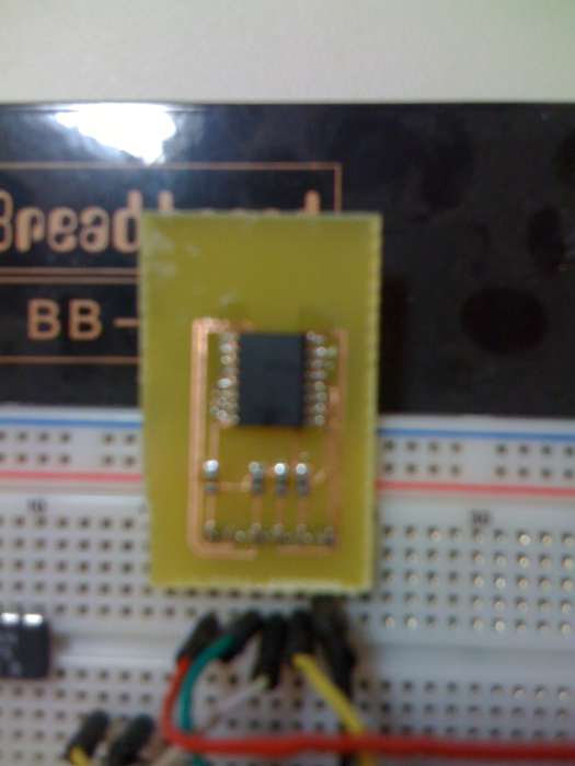
The next step was to start working on the real board. I had known all along I wanted to make a single board that would fit inside the black sleeve and I knew I wanted it to be surface mount. I really enjoy working with surface mount components and I knew I’d need to use small components to get everything I wanted in the sleeve. This took a pretty long time. It was the most complex circuit I had ever designed and I ended up adding a lot more to it than I expected to. After working on keeping time in the Arduino for a while I decided it just was not accurate enough for me and I decided to add a DS3231 real time clock. This chip basically has everything needed to keep super accurate time and it’s easy to communicate with. So, I ordered up some free samples and went back to the garage to build a breakout board for that chip.

After getting this board made and soldered up I was able to start using it with the Arduino to handle time keeping and things really started to come together. At this point I had this giant mess on my desk consisting of an Arduino, a breadboard holding the boost converter circuit, another breadboard holding the click chip and the tube + driver board. I soon added some long wires and a rotary encoder to the mess and I finally had all the major components of the clock actually on my desk and working. I wish I had a picture of the mess.
Mess or not, this allowed me to write all the code I needed to run the clock. The code handles talking to the DS3231 for getting the time, talking to the MAX6921 to drive the tube, drives and monitors the boost converter, read interrupts from the rotary encoder to drive a menu system and a dozen other little things. It’s extremely interrupt driven and I think it’s the nicest AVR code I’ve ever written.
With all the parts together and working it was time to “capture” the schematic. This is what engineers call it when they take the mess on their desk and turn it into a nice, tidy computer drawing. I used Eagle to completely design the circuit and I got to work designing the board to match it. A few weeks later I had a board design and I sent it off to Gold Phoenix for manufacturing.

This board worked really well, except for a few small errors. The main errors were that I forgot to hook up one pin of the CPU which meant I couldn’t put any code on it and the other was that I determined I needed a pull down resistor on my boost controller’s MOSFET for protection. I soldered these fixes on manually and put the board together and I finally had a clock!
This board allowed me to do all the final bug fixes and get everything ready to actually build the clock. One big problem though was that I had put components too close to the four holes around the edges and had no way to really bolt the thing down. With the electrical errors in mind and this physical issue I decided to do another version of the board and for fun decided to get the board made black. Another payment to Gold Phoenix and a week of nail biting and I had my final, final board.

While I waited for those boards to show up I ended up redrawing the CAD drawings for the three metal frames. I needed them to be a little bigger to make everything fit nicely. I also determined I needed 1/4″ long versions of the small tubes instead of 1/2″ ones so I made those. I got that work done and eventually the boards and parts showed up. Yesterday I finished final assembly, drilled a few holes in one of the sleeves for the power and rotary encoder, put the thing together and finally, after nearly four months of work I was finished*.
The eagle eyed among you (like anyone is actually still reading) will notice some flaws. I scratched up the right sleeve while drilling it, so it needs to be repainted. I think I’ll repaint both of them and put a layer of clear coat on them for protection. The holes in the back are also sloppy, so the right sleeve will probably get remade completely. The small tubes on the left are longer than the right and I’ll probably fix that today. Just need to cut four smaller ones like the right. And the middle pipes need to be about 1/4″ longer to show the entire display.
Aside from those minor things, the project is done! It was a ton of work, and a ton of learning but it’s been great fun and very rewarding.
Last night, to clear up loose ends, I finally spent some time tracking down an email address for John. I wrote him a long letter explaining all this and he wrote back and was very cool about the whole thing. He asked that I give him credit for the design, which I am very happy to do.
I make no claim to the design of the enclosure. It’s wholly dreamed up and designed by John Pfeiffer at http://blog.giantpachinkomachineofdoom.com/
I’m really glad he designed it, and posted that picture of it and even more so that he was very understanding about my little obsession. I think the enclosure is gorgeous and had I not seen it I never would have started this project.
I’d also like to thank Ladyada of Adafruit at http://www.adafruit.com. Her clock design gave me the understanding I needed for the electronics side of this project. While the end result is, I think, quite different from her design it’s definitely got it’s roots in the Ice Tube clock kit that she sells. The kit looks great and you should probably go buy one now!
From here, I intend to open source the whole mess. I have some cleaning up to do but once it’s done I’m going to post the code, schematics, CAD drawings, bill of materials and everything I used to build it. Unless you have a machine shop at your disposal, or a massive obsession like myself, you probably won’t make one like it but maybe you’ll see something that gives you the idea to make something even cooler.
There are more photos of the clock and some of the parts at: http://www.flickr.com/photos/vonnieda/sets/72157622935775931/ and below is a video of me showing some of the features of it.


